Industrial Boiler Auxiliary Equipment: Complete BOP Engineering Guide
An industrial boiler represents only one component of a complete steam generation facility. A boiler vessel cannot generate steam or support industrial operations alone. It requires an engineered network of mechanical, thermal, and electrical subsystems to function safely. These integrated subsystems form the industrial boiler auxiliary equipment, also known as Balance of Plant (BOP) systems. […]
Technical Specifications
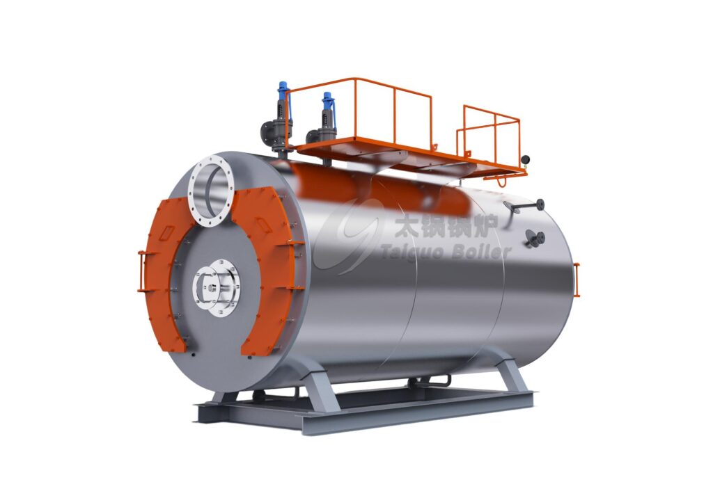
An industrial boiler represents only one component of a complete steam generation facility. A boiler vessel cannot generate steam or support industrial operations alone. It requires an engineered network of mechanical, thermal, and electrical subsystems to function safely. These integrated subsystems form the industrial boiler auxiliary equipment, also known as Balance of Plant (BOP) systems.
This engineering guide examines the major industrial boiler auxiliary equipment categories. We detail their operational functions, technical sizing parameters, and integration points. Engineers, plant managers, and procurement teams will learn how auxiliary subsystems impact boiler lifespan, thermal efficiency, and operational safety.
What Is Boiler BOP Equipment?
In power and thermal engineering, Balance of Plant (BOP) refers to all supporting components and auxiliary infrastructure required to operate the primary boiler unit.
Engineers draw a strict distinction between the core pressure vessel and the surrounding boiler BOP equipment:
- Main Boiler Unit: The pressure vessel, combustion chamber (furnace), boiler drum, and heat exchange tubes (fire-tube or water-tube bundles).
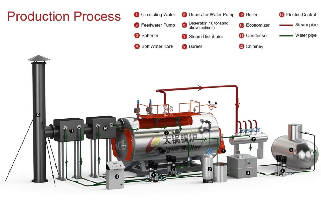
- Boiler Auxiliary Systems (BOP): The burner system, feedwater pumps, deaerator, water softener or reverse osmosis (RO) units, economizer, steam distribution headers, blowdown recovery tanks, emissions ducting, and automated PLC management consoles.
Without matched auxiliary systems, a boiler suffers from thermal shock, rapid internal scaling, fuel waste, and severe safety hazards. Specifying balanced BOP equipment guarantees that fuel, water, air, and steam circulate under monitored, stable thermodynamic conditions.
Main Industrial Boiler Auxiliary Equipment: Feedwater and Water Treatment
Water is the primary working fluid in a steam plant. Untreated water contains dissolved minerals and atmospheric gases that quickly corrode or foul boiler steel. Feedwater and treatment auxiliaries condition, preheat, and inject water into the boiler shell at high pressures.
1. Water Treatment Systems (Softener and RO)
Raw municipal or borehole water carries calcium, magnesium, and dissolved silica. When water boils into steam, these minerals precipitate onto boiler tubes to form scale. Just 1 mm of scale increases fuel consumption by up to 2% to 3% because it insulates the heat transfer surface.
Standard industrial boiler accessories for water treatment include:
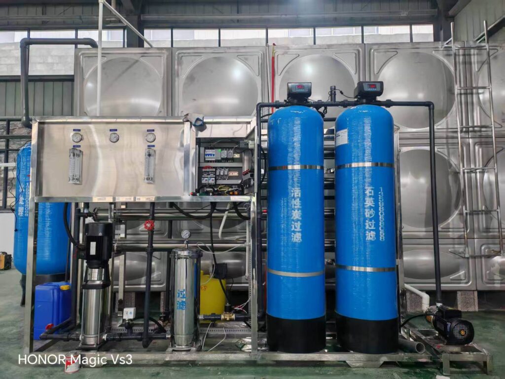
- Twin-Alternating Water Softeners: Use ion-exchange resins to swap scale-forming calcium and magnesium ions for sodium ions. Twin tanks ensure continuous soft water delivery during backwash regeneration.
- Reverse Osmosis (RO) Units: Use semi-permeable membranes under high pressure to remove up to 98% of total dissolved solids (TDS) and silica. Plants operating high-pressure boilers select RO units to minimize chemical blowdown rates.
- Chemical Dosing Skids: Meter precise amounts of oxygen scavengers, scale inhibitors, and pH adjusters directly into the feed line.
2. Atmospheric Feedwater Tank
The feedwater tank acts as a bulk storage buffer between external water treatment supplies and continuous boiler consumption.
- Holding Capacity: Sized to hold 1 to 2 hours of boiler steaming capacity at maximum continuous rating (MCR).
- Condensate Collection: Acts as the primary collection manifold for hot condensate returning from factory processes.
- Thermal Layering: Blending fresh makeup water with returned condensate preheats the water. This reduces fuel use and protects the boiler from thermal shock.
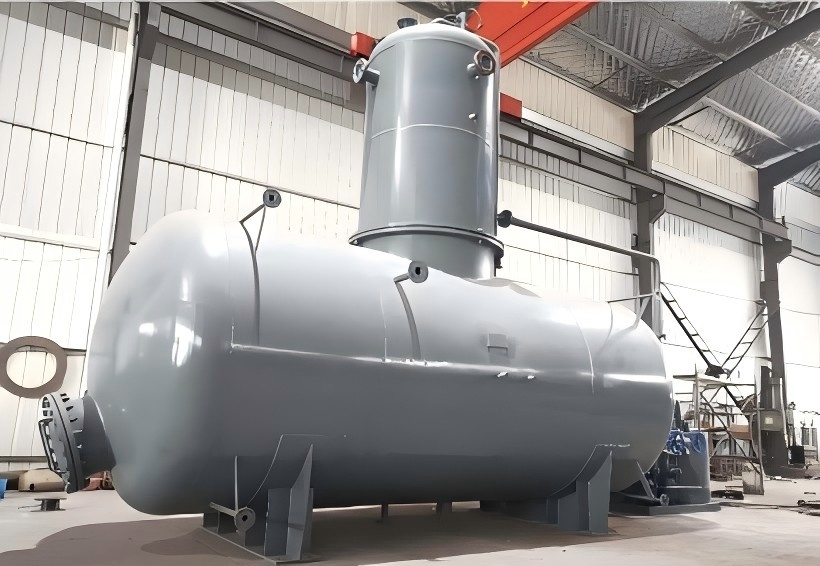
3. Deaerator (Thermal and Spray-Tray Systems)
Dissolved oxygen and free carbon dioxide in feedwater create aggressive pitting corrosion along boiler tubes and economizer coils. A deaerator removes these non-condensable gases mechanically using steam stripping.
Industrial steam plants deploy two major deaerator types:
- Spray-Tray Deaerators: Spray incoming water into fine droplets over internal stainless-steel trays, exposing it to rising low-pressure steam.
- Pressure-Vessel Scrubbers: Heat feedwater to saturation temperature (typically 102°C to 105°C at 0.2 to 0.5 bar gauge). Because gas solubility drops to zero at boiling temperatures, oxygen content drops below 7 parts per billion (0.007 ppm).
Low-pressure boiler installations that lack a mechanical deaerator must maintain high feedwater tank temperatures (80°C to 85°C) and inject chemical oxygen scavengers (such as sodium sulfite) to protect system surfaces.
4. Boiler Feedwater Pumps
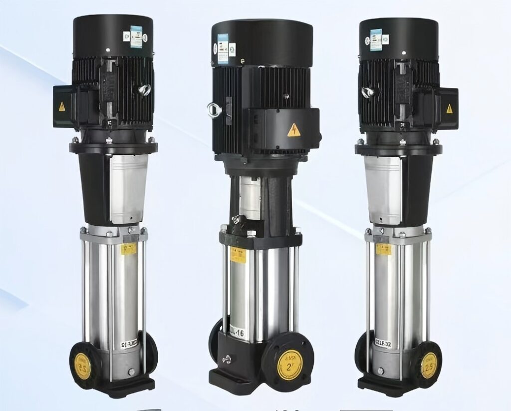
Boiler feedwater pumps transfer water into a pressurized steam vessel. They must overcome boiler operating pressure, pipe friction, valves, and static head.
- Multi-Stage Centrifugal Design: Pumps employ multi-stage impellers in series to produce discharge pressures that exceed the boiler design safety valve setting by 15% to 25%.
- Redundancy Configurations: Industrial design codes require at least two identical pumps: One Duty Pump and One Dedicated Standby Pump. If the primary pump fails or trips on electrical overload, the standby unit starts automatically.
- Speed Control (VFD): Modern plants pair pump motors with Variable Frequency Drives (VFDs) and modulating feedwater valves. This maintains precise water level control across variable plant loads and cuts motor electrical consumption.
Boiler Fuel and Combustion Auxiliary Systems
Combustion auxiliaries deliver fuel and air to the furnace in exact ratios. They extract maximum thermal energy while limiting unburned fuel and harmful emissions.
1. Natural Gas Trains and Burners
For plants running a gas-fired steam boiler, the fuel train regulates gas pressure and protects against leaks or explosions.
- Electronic Air-Fuel Ratio Control: Replaces mechanical linkages with independent servomotors for fuel valves and combustion air dampers. This keeps excess oxygen levels between 2% and 3% across the firing range.
- Flame Safeguard Sensors: Ultraviolet (UV) scanners or flame ionization rods instantly detect flame loss, triggering an emergency gas shutoff within 1 to 2 seconds.
2. Liquid Fuel Supply Systems (Diesel and Heavy Fuel Oil)
Liquid fuel systems require pressurized handling and filtration:
- Fuel Unloading and Storage Tanks: Day tanks and bulk storage vessels fitted with level switches, vent flame arrestors, and leak containment bunds.
- Duplex Fuel Strainers: Continuous filtration skids that switch filters without interrupting boiler firing.
- Atomizing Pumps and Preheaters: Deliver fuel to the burner tip at regulated pressures. Heavy oils require inline preheaters (electric or steam coils) to lower viscosity down to 15–20 cSt for clean atomization.
3. Biomass Fuel Handling Auxiliaries
Solid fuel systems on an industrial biomass boiler require robust mechanical transport to feed fuels like wood chips, pellets, or agricultural waste:
- Storage Silos and Live-Bottom Hoppers: Feature hydraulic agitators and vibratory dischargers to prevent fuel bridging.
- Mechanical Conveyors: Enclosed screw feeders, bucket elevators, and scrapers transport fuel into the boiler hopper.
- Rotary Air-Lock Valves: Prevent combustion air and flue gases from backfiring into fuel feed chutes.
- Automated Ash Removal: Water-cooled drag chains and de-ashing screws continuously extract bottom ash and fly ash into disposal bins.
Steam-Side Auxiliary Equipment
The boiler produces steam, but auxiliary piping components regulate, monitor, and transport that energy to consumer equipment.
1. Steam Header (Distribution Manifold)
The steam header is a fabricated carbon-steel pressure vessel positioned directly downstream of the boiler main steam stop valve.
- Pressure Stabilization: Acts as a central buffer that dampens line pressure pulsations caused by cycling batch loads.
- Multi-Boiler Balancing: Connects two or more boilers in parallel to distribute total steam load across the facility.
- Moisture Separation: Drops line velocity to 10–15 m/s, allowing entrained water droplets to fall out of the steam flow and drain through bottom traps.
2. Safety Relief Valves (SRV)
Safety relief valves are the ultimate mechanical protection against vessel overpressure. Sized according to ASME Section I or local PED codes, these direct spring-loaded valves open automatically when pressure exceeds the Maximum Allowable Working Pressure (MAWP). Full-lift safety valves must discharge 100% of maximum generated steam without allowing internal pressure to climb more than 6% above the setpoint.
3. Pressure Reducing Stations (PRV)
Boilers generate steam at high pressure to minimize pipe diameters and reduce steam bubbles in the drum. However, process heat exchangers require lower pressures to capture higher latent heat values and stay within vessel ratings. Self-acting or pneumatic pressure-reducing valves step line pressure down while maintaining set downstream limits.
4. Steam Traps and Condensate Return Systems
Condensate that sits inside steam piping causes water hammer, accelerates internal corrosion, and restricts thermal transfer.
- Steam Traps: Automatic valves that discharge condensate, air, and non-condensable gases while blocking live steam. Plants select mechanical (float), thermodynamic (disc), or thermostatic traps depending on the application.
- Condensate Return Skids: Insulated receiving tanks with high-temperature pumps that capture pure, hot condensate and pump it back to the boiler feedwater tank. Recovering condensate cuts both raw makeup water demand and fuel consumption.
Heat Recovery: Economizers and Condensing Units
Standard flue gases leave boiler tubes between 180°C and 250°C, carrying away significant sensible heat. Heat recovery units capture this thermal energy to improve system performance.
| Auxiliary Heat Recovery Device | Typical Installation Location | Heat Exchange Mechanism | Efficiency Gain |
|---|---|---|---|
| Standard Bare-Tube Economizer | Directly at boiler flue gas exit | Transfers flue gas heat into pressurized boiler feedwater | +3% to +5% |
| Finned-Tube Economizer | Flue gas duct before stack | Spiral fins expand surface area to preheat boiler feedwater | +4% to +6% |
| Condensing Heat Exchanger | Downstream of primary economizer | Drops gas below dew point (55°C) to capture latent heat | +5% to +8% (Gas Only) |
| Air Preheater (APH) | Flue duct to combustion air intake | Uses exhaust gas to preheat incoming burner combustion air | +2% to +4% (Biomass/Coal) |
Installing an economizer to lower flue gas temperature by 20°C boosts overall boiler thermal efficiency by approximately 1%. Matching heat exchangers with boiler capacity directly reduces long-term gas steam boiler operating cost profiles.
Chimney and Flue Gas Systems
Flue gas systems safely vent combustion products outside the facility according to local environmental regulations.
- Exhaust Ducts and Breaching: Heavy-duty, insulated carbon or stainless steel ductwork designed with expansion joints to handle thermal expansion and minimize backpressure on the burner fan.
- Exhaust Chimney (Stack): Self-supporting, guy-wired, or tower-supported stacks built to meet local emission dispersion heights.
- Induced Draft (ID) and Forced Draft (FD) Fans: Balanced draft systems rely on FD fans to push fresh air into the burner, while ID fans pull exhaust gases through economizers, baghouses, and wet scrubbers.
- Continuous Emissions Monitoring (CEMS): Analyzers that track real-time flue gas components like oxygen, CO, NOx, SO2, and opacity to document regulatory compliance.
Boiler Blowdown and Water Quality Systems
Boiler water continually evaporates into pure steam vapor, leaving dissolved minerals behind in the drum. If neglected, mineral concentrations rise, causing water foaming, steam carryover, and hard scale formation along heat transfer tubes.
Auxiliary blowdown systems control and lower mineral levels:
Continuous Surface Blowdown: An automated TDS probe continuously samples water conductivity near the water line. When TDS exceeds target levels (e.g., 3,000 ppm), an actuator opens a needle valve to drain mineral-heavy water.
Intermittent Bottom Blowdown: Large-bore, quick-opening valves located at the lowest point of the pressure vessel. Operators cycle these valves for 5–10 seconds per shift to eject accumulated sludge and precipitated scale.
Blowdown Flash Vessels and Coolers: Flash tanks separate blowdown effluent into flash steam (which returns to the deaerator) and high-temperature water. A shell-and-tube or plate heat exchanger then preheats cold makeup water. This drops discharge water temperatures below 60°C, complying with municipal wastewater disposal regulations.
Control, Electrical, and Safety Systems
Modern boiler control panels consolidate autonomous burner, pump, and valve behaviors into a unified management architecture.
- Programmable Logic Controllers (PLC): Industrial-grade microprocessors (such as Siemens, Schneider, or Allen-Bradley) that monitor live process variables: steam drum pressure, water levels, fuel flows, and exhaust temperatures.
- Touchscreen HMI Consoles: Allow operators to monitor process loops, set operating pressures, adjust PID tuning values, track diagnostic alarms, and review historical operating trends.
- Fail-Safe Redundant Level Controls: Mechanical float switches paired with conductivity probes or differential-pressure level transmitters provide reliable water monitoring. If water levels drop below safe minimum points, dual low-water cutoff switches immediately shut down the burner to prevent dry-firing and vessel explosions.
- Emergency Stop (ESD) Integration: Hardwired safety trips bypass software logic to cut fuel supply valves and isolate electrical power during plant emergencies.
Typical Industrial Steam Boiler BOP Layout
To visualize balance of plant interactions, review the engineering schematic below. Notice how raw water, fuel, electrical power, and heat recovery circuits operate alongside the primary steam generation vessel.
Every fluid loop requires balanced engineering sizing. A disruption across any single auxiliary component directly interrupts overall plant steam production.
Boiler Auxiliary Equipment by Boiler Type
Auxiliary equipment specifications change depending on fuel selection and thermodynamic design parameters.
| Boiler Type | Primary Fuel / Energy | Standard Auxiliary Equipment Package | Typical Applications |
|---|---|---|---|
| Gas Steam Boiler | Natural Gas, LPG, Biogas | Multi-stage gas train, electronic servo-burner, modulating feed pumps, economizer, stainless chimney | Food processing, pharmaceuticals, commercial textiles, chemical facilities |
| Diesel Steam Boiler | Light Diesel, HFO | Fuel storage day tank, duplex pump/strainer skid, preheater coils, mechanical burner, blowdown vessel | Marine propulsion, remote mining, export operations lacking utility gas |
| Biomass Boiler | Wood Pellets, Agrowaste, Palm Shell | Enclosed screw conveyor, rotary airlock, underfeed stoker, cyclone dust collector, baghouse filter, ID fan | Timber processing, palm oil refineries, paper mills, agricultural processing |
| Thermal Oil Heater | Gas, Light Oil, Solid Biomass | High-temp circulation pumps, nitrogen blanket expansion tank, deaerator vessel, oil filter skid | Asphalt terminals, chemical synthesis, polymer extrusion, industrial coating |
| Electric Steam Boiler | 380V–480V 3-Phase Power | SCR power controllers, immersion heating elements, compact feedwater skid, automated drain setup | Clean laboratories, hospital sterilization units, high-purity processing rooms |
Reviewing our guides on complete industrial steam boiler system configurations helps clarify how specific fuel selections alter site civil preparation and mechanical engineering needs.
How to Select and Size Boiler Auxiliary Equipment
Engineers select and balance BOP auxiliary equipment using a step-by-step sizing approach:
- Define Continuous and Peak Steam Demands: Size the boiler and its auxiliary equipment for both continuous baseloads and peak process spikes. Use our industrial boiler capacity calculation reference to model dynamic operational swings.
- Determine System Operating Pressure: Set operating pressure based on the highest pressure needed by plant process equipment, factoring in distribution pipe pressure drops.
- Perform a Laboratory Raw Water Analysis: Test raw water samples for total hardness, silica, chlorides, and TDS to specify suitable water treatment equipment (such as softeners or RO membranes).
- Size the Feedwater Storage and Deaerator: Ensure the feedwater tank holds 1 to 2 hours of maximum steaming volume. The deaerator must strip dissolved oxygen down below 0.007 ppm under peak flow conditions.
- Calculate Feedwater Pump Operating Margins: Specify pump flow rates at 1.25 times maximum boiler evaporation capacity. Set pump head pressure 15% to 25% above safety valve relief settings to ensure reliable injection.
- Evaluate Fuel Supply Parameters: Measure gas pipeline pressures or liquid fuel viscosity at the boiler room boundary to properly select gas trains, strainers, and preheaters.
- Calculate Flue Gas Heat Recovery Economics: Evaluate fuel savings against boiler return water temperatures to select between a standard economizer or a condensing heat recovery system.
- Integrate Controls with Plant Systems: Standardize control protocols (Modbus, Profibus, Ethernet/IP) to link the boiler PLC with the plant SCADA control architecture.
Applying disciplined engineering during auxiliary selection prevents undersized pumps, water carryover, and unexpected plant shutdowns. Reviewing our industrial boiler room design guide will help coordinate floor layouts, maintenance clearances, and pipe rack runs.
How Much Does Boiler Auxiliary Equipment Cost?
Procurement teams often ask what percentage of total capital expenditure (CAPEX) goes toward auxiliary equipment. While an entry-level package might add 25% to the base vessel price, a fully automated, high-efficiency BOP installation can exceed 100% of the bare boiler cost.
Costs scale based on operational requirements rather than flat percentages:
- Fuel Train Complexity: Standard commercial gas trains cost substantially less than dual-fuel (gas/oil) automated systems equipped with hazardous-area explosion-proof valves.
- Water Treatment Automation: Basic ion-exchange softeners are budget-friendly, whereas industrial Reverse Osmosis skids fitted with automated chemical dosing represent a larger investment.
- Heat Recovery Investment: Standard carbon steel economizers have a modest cost, while stainless steel condensing heat recovery modules require higher upfront capital. However, condensing units deliver strong operational savings, often paying for themselves in fuel reduction within 6 to 18 months.
- Emissions Abatement Technology: Facilities subject to strict air-quality mandates require baghouse dust collectors, flue gas recirculation (FGR) systems, or selective catalytic reduction (SCR) skids, which add significant auxiliary expense.
Evaluating lifetime fuel and maintenance costs gives a clearer financial picture than focusing solely on upfront purchase prices.
Common Mistakes When Selecting Boiler Auxiliaries
Small oversights during auxiliary equipment selection frequently cause operational bottlenecks after commissioning:
- 1. Sizing Boiler Output Without Checking Peak Surges: Selecting equipment solely on average hourly steam demand causes low-water trips and pressure drops when batch processes start up. Size auxiliary feed pumps and headers to absorb these peak surge periods.
- 2. Ignoring Feedwater Temperature Limitations: Feeding boilers with cold water (under 60°C) causes internal thermal shock, strains welded joints, and leads to fireside acid condensation on tubes. Always use preheated water.
- 3. Neglecting Feedwater Pump Redundancy: Running a plant with only one feedwater pump risks total facility shutdowns during routine seal or motor maintenance. Always specify one duty pump and one fully plumbed standby pump.
- 4. Discharging Unrecovered Condensate: Venting hot condensate directly to sewer lines wastes treated water, thermal energy, and expensive water-treatment chemicals. Modern facilities prioritize high-efficiency condensate return systems.
- 5. Skipping Continuous TDS Monitoring: Relying solely on manual blowdown valves leads to swings in water quality. Automated surface blowdown skids keep TDS levels stable while preventing excessive hot water waste.
- 6. Sourcing Boilers and Auxiliaries in Isolation: Purchasing components from disconnected suppliers often creates mismatched pipe flanges, inconsistent electrical voltages, and conflicting PLC communication protocols.
Frequently Asked Questions (FAQ)
What is BOP in an industrial boiler system?
BOP stands for Balance of Plant. In an industrial boiler facility, BOP refers to all auxiliary components, support infrastructure, and subsystems outside the central boiler pressure vessel required to generate steam safely and reliably.
What are common boiler auxiliary equipment components?
Major boiler auxiliary equipment includes water softeners, reverse osmosis systems, deaerators, feedwater tanks, multi-stage boiler feed pumps, burner assemblies, fuel trains, economizers, steam distribution headers, safety valves, blowdown tanks, and PLC control panels.
Why is water treatment equipment necessary for a steam boiler?
As boiler water boils into steam, dissolved minerals like calcium, magnesium, and silica stay behind in the vessel. Without water treatment, these minerals form hard scale across heat transfer tubes, causing tube overheating, metal blistering, reduced efficiency, and potential vessel explosions.
What is the function of a boiler feedwater pump?
A boiler feedwater pump delivers treated water into the pressurized boiler shell. The pump must generate sufficient discharge head to overcome internal vessel steam pressure, line friction losses, and piping elevation differences.
What does an economizer do on an industrial boiler?
An economizer is a gas-to-water heat exchanger installed in the exhaust duct. It captures waste heat from hot flue gases to preheat incoming feedwater before it reaches the boiler, improving overall thermal efficiency by 3% to 6%.
Why do boilers need a deaerator?
A deaerator mechanically removes dissolved oxygen and carbon dioxide from boiler feedwater using steam stripping. Removing these gases prevents pitting corrosion across boiler tubes, drum shells, and economizer coils.
What is the purpose of a steam header?
A steam header is a distribution manifold installed at the boiler plant outlet. It stabilizes line pressure, balances output across multiple boilers, drops line velocities to remove moisture droplets, and distributes steam to individual plant processes.
How does continuous blowdown differ from bottom blowdown?
Continuous surface blowdown drains water from near the operating water level to keep dissolved solids (TDS) within target limits. Intermittent bottom blowdown quickly opens valves at the vessel bottom to flush out precipitated sludge and loose sediment.
Engineering Complete Boiler Island Solutions
A reliable steam plant requires more than simply positioning a boiler shell on a concrete foundation. Durable, efficient operation depends on balanced thermal, fluid, and electrical auxiliary subsystems.
At CN MIRACLE &Taiguo Boiler, our engineering team designs and manufactures high-efficiency boiler plants and fully integrated BOP auxiliary skids tailored to international export requirements. From matched fuel trains and automated deaerators to turn-key, pre-piped containerized boiler rooms, we deliver complete thermal energy solutions designed for your plant’s exact operating conditions.
Discussing your project parameters, request auxiliary equipment sizing schedules, or review our comprehensive boiler engineering services.