
How to Design a Complete Industrial Steam Boiler System
Industrial process plants rely on dry, high-enthalpy steam for continuous manufacturing. However, plant developers often make a critical error during initial engineering: they treat the steam boiler as an isolated appliance. They order a pressure vessel, place it on a concrete pad, and connect generic utility lines. This shortcut leads to major operating problems. High-performance […]
Get Instant Quote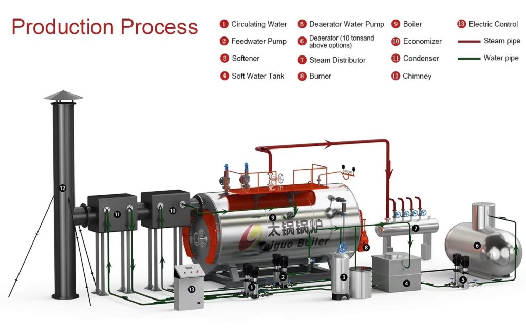
Technical Specifications
Industrial process plants rely on dry, high-enthalpy steam for continuous manufacturing. However, plant developers often make a critical error during initial engineering: they treat the steam boiler as an isolated appliance. They order a pressure vessel, place it on a concrete pad, and connect generic utility lines.
This shortcut leads to major operating problems. High-performance industrial steam boiler system design requires integrating thermal generation, feedwater conditioning, fuel combustion trains, fluid distribution networks, and automated safety interlocks into a unified thermodynamic circuit. Sizing or designing any single sub-component incorrectly creates system-wide bottlenecks. Inadequate water softening fouls heat transfer surfaces with scale within months. Undersized steam distribution headers cause massive pressure drops during peak process draws. Discarding hot condensate squanders 10% to 15% of annual boiler fuel budgets.
This technical engineering guide walks through the step-by-step design of a complete industrial steam system design. It outlines key equipment selections, thermodynamic calculations, balance-of-plant auxiliary equipment, and automated control requirements for modern industrial plants.
1. What Is an Industrial Steam Boiler System?
An industrial steam boiler system is a closed-loop energy conversion and mass-transfer plant. It converts the chemical energy of fuels or electrical energy into pressurized thermal steam, delivers that heat across factory floor processes, and returns recovered fluid back to the thermal generation core.
▼
▼
▼
▼
▼
A complete system integrates eleven core subsystems:
- Steam boiler pressure vessel (fire-tube, water-tube, or electric heating core)
- Burner or combustion grate system (natural gas, light/heavy fuel oil, or solid biomass)
- Fuel storage, conditioning, and delivery train
- Feedwater pumping and storage system
- Feedwater purification and chemical water treatment system
- Main steam distribution header and manifold
- Factory steam piping distribution network and pressure-reducing stations
- Condensate drainage, trapping, and collection return system
- Continuous and intermittent bottom blowdown heat recovery system
- Flue gas extraction, economizer heat recovery, and chimney stack
- Centralized control panel, burner management system (BMS), and safety trips
Core Engineering Insight: A boiler is only one part of a complete industrial steam system. A boiler cannot deliver dry, stable steam efficiently without properly designed balance-of-plant auxiliary equipment.
2. Start With Steam Demand and Process Requirements
Never select equipment based on assumptions or simple nameplate capacity matching. Every high-efficiency industrial steam boiler system design begins with an audit of the facility’s production profile.
Engineers evaluate several core operating parameters:
- Required Steam Output Capacity: Calculate both the daily mass consumption and the simultaneous peak hourly steam rate.
- Operating Steam Pressure: Match boiler pressure to the single highest-pressure consumer on site, adding distribution line drops.
- Steam Enthalpy and Quality: Determine whether machines require saturated steam (for latent-heat cooking, heating, and vulcanizing) or superheated steam (for power generation and long distribution runs).
- Operating Hours and Shift Cycles: A plant operating on a single 8-hour shift has entirely different start-up and thermal stress profiles than a plant running 24/7 continuous operations.
- Simultaneous Coincidence (Diversity Factor): Determine how many batch processes will ramp up heat concurrently.
- Factory Expansion Allowances: Reserve header space, pump capacity, and floor area for planned production line expansions over a 3- to 5-year window.
- Local Fuel Availability: Check local pipeline gas flow, local electrical substation limits, and biomass supply chains.
Understanding these requirements connects plant production needs directly to utility sizing. Engineers must establish exact peak steam demand profiles to size the central system properly.
3. Select the Right Industrial Steam Boiler
Selecting the boiler type establishes the baseline footprint, civil engineering needs, and fuel costs for the entire facility.
| Boiler Type | Primary Industrial Use Case |
|---|---|
| Gas/Oil Fired | Fast load response, strict emissions compliance, and high automation |
| Biomass Fired | Low-cost agricultural fuel regions, steady baseload |
| Electric | Compact cleanrooms, zero local emissions, low volume |
| Fire-Tube (WNS) | Low-to-medium pressure (0.8–2.5 MPa), up to 20 TPH |
| Water-Tube (SZL) | High pressure (>2.5 MPa), massive capacity (>20 TPH) |
Gas and Oil-Fired Steam Boilers
Packaged three-pass wet-back fire-tube boilers (such as standard WNS series designs) dominate modern industrial manufacturing. They feature fully modulating burners, compact footprints, and rapid turndown response to match shifting factory steam loads. These units produce dry saturated steam efficiently when connected to pipeline natural gas, LPG, or light diesel fuel.
Biomass Steam Boilers
Solid-fuel boilers (such as SZL double-drum water-tube or DZL shell-type boilers) burn renewable, low-cost biomass materials. They process wood pellets, rice husks, palm kernel shells (PKS), and agricultural residues. Biomass systems require larger footprints for automated feeding hoppers, mechanical chain grates, multi-cyclone dust collectors, and continuous ash removal augers. They suit plants in agricultural regions with abundant, low-cost solid fuel supplies.
Electric Steam Boilers
Electric boilers use immersion heating elements or electrode assemblies to vaporize demineralized water. They operate with zero on-site emissions, require no chimney or fuel lines, and operate quietly with small footprints. However, high commercial electricity tariffs usually restrict electric boilers to cleanroom applications, laboratories, and micro-sampling lines.
Fire-Tube vs. Water-Tube Boilers
- Fire-Tube Boilers: Hot combustion gases pass inside submerged tubes surrounded by a large volume of water. The large water reservoir acts as a thermal flywheel. It cushions against sudden pressure drops during rapid process steam surges. Fire-tube boilers suit capacities between 1.0 and 20 TPH with working pressures up to 2.5 MPa (25 bar).
- Water-Tube Boilers: Water circulates inside small-diameter tubes heated externally by flue gases. Water-tube designs hold less water volume, generate steam rapidly, and safely withstand high pressures. They suit large industrial complexes requiring capacities over 20 TPH or steam pressures exceeding 2.5 MPa.
4. Design the Boiler Feedwater System
The boiler feedwater system purifies raw utility water, stores heated water, and injects it into the pressurized boiler shell.
Water Treatment System
Untreated feedwater damages boiler systems. Dissolved calcium and magnesium ions precipitate onto high-temperature heating surfaces, forming dense scale layers. A mere 1 mm of mineral scale reduces heat transfer by roughly 5%, causing tube metal to overheat and fail.
- Duplex Water Softeners: Ion-exchange softeners remove scaling hardness ions (Ca2+, Mg2+) using sodium-regenerated resin beds. Duplex configurations ensure uninterrupted soft water delivery during resin regeneration cycles.
- Reverse Osmosis (RO) Plants: RO systems remove total dissolved solids (TDS), silica, and chlorides. They prevent foaming, carryover, and stress corrosion cracking in high-pressure boilers.
- Chemical Conditioning Skids: Metering pumps inject oxygen scavengers (such as sodium sulfite or DEHA), alkaline pH buffers, and polymer sludge conditioners directly into the feedwater.
Feedwater Storage and Deaeration Tank
The feedwater tank stores a thermal reserve (typically sized for 1 to 2 hours of maximum boiler steaming capacity). It blends treated cold makeup water with returning hot condensate.
- Thermal Deaeration: Maintaining atmospheric feedwater temperatures between 85°C and 105°C strips dissolved corrosive gases (O2 and CO2) out of the water. This eliminates oxygen pitting corrosion across boiler metal and steam lines.
- Tank Elevation: Feedwater tanks are usually elevated on steel mezzanines above feed pumps. Elevated tanks provide adequate Net Positive Suction Head Available (NPSHA), which prevents pump impeller cavitation when handling hot water.
Boiler Feedwater Pumps
Industrial systems require multi-stage vertical centrifugal pumps rated for continuous operation at high pressures and temperatures.
- Pump Sizing: Pumps must deliver at least 1.25 to 1.5 times the maximum continuous rating (MCR) of the boiler at a discharge pressure exceeding the boiler design pressure by 1.5 to 2.5 bar.
- Redundancy: Always install an N+1 pump configuration (one primary operational pump and one fully piped, auto-starting standby pump).
- Modulating Control: Variable frequency drive (VFD) pumps match water intake directly to steam discharge rates. This avoids thermal shock and stabilizes internal water levels.
5. Design the Fuel Supply System
A safe fuel supply delivers clean, pressure-regulated fuel to the combustion equipment under strict safety interlocks.
Gas and Oil Combustion Trains
Gas supply trains include gas strainers, high-pressure regulators, slam-shut safety valves, and double block-and-bleed solenoid valves. Pressure switches confirm that pipeline gas pressure remains within certified operational windows before the burner management system (BMS) allows ignition. Oil systems require fuel preheating loops, suction filters, high-pressure pumps, and backpressure regulating valves to atomize viscous fuels cleanly.
Solid Biomass Handling Systems
Biomass fuel requires robust mechanical handling equipment. Systems use outdoor storage yards, belt conveyors, bucket elevators, and daily surge hoppers above the boiler. Rotary airlock valves seal the hopper, preventing back-drafting and furnace fires from creeping up the fuel delivery chutes. Hydraulic rams or variable-speed feeding screws meter pellets or husks onto the moving combustion grate.
6. Design the Steam Distribution System
The steam distribution system delivers dry, clean steam from the boiler to distant factory processes with minimal pressure and heat losses.
│
│
│
▼
▼
▼
▼
▼
▼
Main Steam Header
The steam header acts as a pressure buffer and distribution manifold. Size headers for low steam velocities (10 to 15 m/s) to encourage moisture separation. Take off process branches from the top of the header with 90-degree sweep bends. This prevents pooled water from washing into active production lines during valve operations.
Transmission Piping Sizing and Sizing Physics
Select distribution pipe diameters based on recommended flow velocities:
- Saturated Steam Lines: Design for velocities between 25 and 35 m/s. Undersized pipes create severe line friction drops and noise. Oversized pipes increase installation costs and expand thermal surface radiation losses.
- Superheated Steam Lines: Allow velocities of 35 to 50 m/s for long-distance utility headers.
Steam Trapping and Drainage Stations
As steam travels along distribution lines, ambient heat loss causes condensation. Water droplets traveling at high speed create destructive water hammer that ruptures valves, fittings, and instruments.
- Install dedicated collecting drain pockets with float or thermodynamic steam traps every 30 to 50 meters along straight pipe runs.
- Place drain pockets at the base of every vertical riser and directly upstream of every control valve and isolation shutoff.
Pressure-Reducing Valve (PRV) Stations
Distribute steam at elevated pressures (0.8 to 1.0 MPa / 8 to 10 bar) to keep transmission pipe diameters small and line heat losses low. At process equipment connections, install PRV stations to reduce steam pressure to operating levels (0.15 to 0.4 MPa / 1.5 to 4 bar). Lower pressure increases the usable latent heat enthalpy transferred to the product while protecting delicate equipment seals.
Pipe Insulation and Thermal Expansion
Insulate all steam headers, pipes, valves, and flanges with pre-formed mineral wool or calcium silicate jacketing. Insulation cuts line heat loss by over 90%. Steam pipes expand roughly 1.5 to 2.0 mm per linear meter at standard temperatures. Incorporate engineered expansion loops, directional pipe anchors, and sliding supports to absorb thermal expansion safely without stressing boiler nozzles.
7. Design the Condensate Return System
Condensate forms when steam gives up its latent heat inside process heat exchangers. Discarding this hot condensate is one of the costliest mistakes in plant engineering.
Why Recover Condensate?
- Direct Fuel Conservation: Condensate returns to collection tanks at 75°C to 95°C. Fresh makeup water enters plants at ambient temperatures (15°C to 25°C). Recovering hot condensate saves approximately 1% in fuel for every 6°C rise in feedwater temperature, yielding 10% to 15% lower fuel consumption.
- Chemical and Water Savings: Condensate is pure distilled water. Returning it cuts municipal water bills and slashes water softening and conditioning chemical expenses.
- Lower Blowdown Losses: Pumping clean condensate into the boiler lowers TDS levels, reducing costly hot water blowdown purging.
Condensate System Architecture
Condensate loops require careful mechanical design:
- Size return pipes generously to handle flash steam without creating excessive backpressure on traps.
- Slope return lines downward toward a vented condensate receiver tank.
- Install high-temperature, mechanical or electric return pumps to transfer collected condensate back into the elevated boiler feedwater deaerator.
8. Design the Boiler Blowdown System
As water boils into pure vapor, non-volatile minerals remain behind in the liquid water. Without blowdown, dissolved solids concentrate, causing water foaming, level gauge instability, and wet steam carryover.
Shell
1. Continuous Surface Blowdown (TDS Control)
Install a motorized needle control valve connected to a conductivity sensor near the boiler water line. The system purges small amounts of concentrated brine continuously. Route this water through a flash tank or shell-and-tube heat exchanger to preheat cold incoming makeup water.
2. Intermittent Bottom Blowdown (Sludge Removal)
Heavy precipitates, scale flakes, and chemical sludge settle to the bottom of the boiler pressure vessel. Plant operators open fast-acting, high-pressure bottom blowdown valves for 5 to 10 seconds per shift. This sudden purge scours sludge deposits out of the vessel floor.
3. Blowdown Vessel and Cooling Pit
High-temperature blowdown water cannot discharge directly into public sewers. Environmental laws require routing blowdown into an ASME-rated blowdown vessel or cooling pit. The vessel vents flash steam safely to the atmosphere, while a thermostatically controlled cold-water quench valve cools liquid discharge below 40°C before entering public drains.
9. Design the Flue Gas and Chimney System
The exhaust system expels combustion gases while recovering remaining sensible heat before discharge.
Economizer
Flue Gas Economizers
Exhaust gases leave fire-tube boilers at temperatures between 200°C and 250°C. Installing an external finned-tube condensing economizer captures this waste heat to preheat incoming feedwater.
- Lowering exhaust flue gas temperature by 20°C boosts overall boiler thermal efficiency by approximately 1%.
- Adding a high-performance condensing economizer raises standard boiler efficiency from 90% to over 95%.
Ductwork and Chimney Stack Architecture
- Draft Management: Size the exhaust ducting and stack diameter to balance backpressure against natural thermal draft. Excess friction backpressure strains burner fans, while excessive negative draft pulls heat out of the furnace too quickly.
- Corrosion Protection: Condensing economizers generate acidic moisture when cooling flue gases below dew point. Fabricate ducting and chimney liners from 316L stainless steel with condensate drainage collection ports.
- Stack Sizing and Regulations: Stack heights must comply with local environmental laws to disperse trace emissions safely.
Note: Final chimney height, draft sizing, and emission limits must follow project location rules and national environmental codes.
10. Boiler Control and Safety System
A high-pressure steam boiler system requires an integrated, failsafe control architecture to protect personnel and equipment.
Boiler Control Architecture
Modern industrial systems use programmable logic controllers (PLCs) with touchscreen Human-Machine Interfaces (HMIs). The panel automates boiler operation:
- Continuous Drum Level Modulation: Controls modulating feedwater valves or VFD pumps using single-element or three-element level monitoring.
- Modulating Combustion Control: Balances air dampers and fuel valves to maintain peak combustion efficiency across the burner’s operating range.
- Automated Burner Management System (BMS): Manages pre-purge air flushing, electrical spark ignition, flame verification, and controlled shutdowns.
Life-Safety Protection Interlocks
Safety systems operate through hardwired, fail-safe electromechanical circuits that trip independently of the PLC:
- Overpressure Protection: Dual spring-loaded safety relief valves must vent 100% of maximum steam generation capacity without allowing boiler pressure to exceed design limits by more than 10%.
- Low-Water Fuel Cutoff (LWFCO): Two independent water level sensors (conductivity probes or float switches) shut off the fuel supply if water drops below the safe operating line. The secondary LWFCO acts as a hard safety lockout that requires a manual reset by an operator.
- Optical Flame Monitoring: UV or infrared sensors detect pilot and main burner flames. If the flame goes out, the BMS closes the safety shut-off valves within 2 to 4 seconds, preventing unburned fuel from accumulating in the hot furnace.
- Emergency Push-Button Stations: Mount emergency shutoff buttons outside every boiler room exit door to immediately cut all fuel and electrical power during an incident.
11. Integrating All Boiler System Components
A successful project links all nine mechanical circuits into a coordinated process plant.
Heat Exchanger
Treatment System
Deaerator Skid
& Heat Exchangers
Fluid balance governs this design: the water system feeds the boiler; combustion boils water into steam; the steam header distributes heat to factory machinery; and heat exchangers return condensate to the feedwater core. Integrating these systems cleanly ensures stable operating pressures, high fuel efficiency, and long equipment life.
12. Industrial Steam Boiler System Example
This turnkey engineering model illustrates equipment selections for a representative mid-sized processing plant.
Project Baseline Assumptions
- Primary Manufacturing Application: Food processing and packaging
- Operating Hours: 16 hours/day (two working shifts, 300 days/year)
- Average Steam Demand: 6.5 TPH
- Peak Instantaneous Coincident Demand: 8.5 TPH
- Required Factory Process Pressure: 0.35 to 0.40 MPa (3.5 to 4.0 bar)
- Fuel Selection: Pipeline natural gas
Subsystem Engineering Specifications
| Subsystem Component | Engineering Specification | Design Rationale |
|---|---|---|
| Primary Boiler | 10.0 TPH WNS three-pass fire-tube boiler | Provides margin over 8.5 TPH peak load |
| Boiler Operating Pressure | 1.0 MPa (10 barg) saturated steam | Allows compact piping; drops to 3.5 bar at machines |
| Combustion System | Fully modulating low-NOx gas burner | Turndown ratio covers shifts from 2.0 to 10.0 TPH |
| Energy Recovery | Condensing stainless steel finned economizer | Cuts flue gas to 95°C, yielding >95% efficiency |
| Water Treatment | Automated duplex softening skid + RO unit | Keeps feedwater hardness below 0.03 mmol/L |
| Deaerator Skid | Atmospheric thermal deaerator at 104°C | Strips O₂ / CO₂ to prevent internal tube pitting |
| Feed Pumps | Two multi-stage vertical pumps with VFDs | 1 duty + 1 standby rated for 15 TPH at 16 barg |
| Steam Header | DN300 manifold with top-entry takeoffs | Buffers velocity below 12 m/s; dries steam output |
| Blowdown Package | Automatic surface TDS valve + blowdown pit | Maintains boiler water TDS below 3,000 ppm |
| Condensate Loop | Pressurized return system recovering 75% | Yields ~12% direct fuel savings on annual gas bills |
Disclaimer: This case study provides an illustrative engineering model. Equipment sizing must match site-specific layout designs, process needs, and local regulations.
13. Boiler Room Layout vs. Complete Industrial Steam Boiler System Design
Plant managers often confuse boiler room layout planning with complete steam system engineering. While related, they address distinct engineering scopes:
| Engineering Focus | Boiler Room Design (Civil & Spatial Focus) | Complete Steam Boiler System Design (Thermodynamic Focus) |
|---|---|---|
| Primary Objective | Safe equipment arrangement inside a building | Complete thermal mass flow, generation, and energy efficiency |
| Key Constraints | Maintenance clearances, door access, structural loads | Enthalpy balance, fluid flow rates, pressure drops, chemistry |
| Core Equipment | Housekeeping pads, lifting monorails, escape doors | Boilers, deaerators, PRV stations, steam traps, heat loops |
| Ventilation Needs | Combustion air intake louvers, heat exhaust relief | Air stoichiometric ratios, excess air modulation, burner fan head |
| Piping Scope | Equipment-to-wall clearances and local header space | Factory-wide distribution piping, insulation, condensate returns |
eview our companion engineering guide on Industrial Boiler Room Design: Layout, Equipment & Safety for in-depth civil spatial rules, structural clearances, and equipment placement strategies.
14. Common Industrial Steam Boiler System Design Mistakes
Avoiding these common engineering and specification mistakes protects capital budgets and prevents costly retrofits:
| Item | Engineering Design Mistake | Direct Operational Risk & Impact |
|---|---|---|
| Mistake 1 | Sizing the boiler to average daily steam demand instead of peak coincident load | Capacity TripSevere boiler pressure drop and carryover during batch startup peaks |
| Mistake 2 | Undersizing main steam pipes, causing high pressure drops and line noise | StarvationExcessive steam velocity (>35 m/s), pipe erosion, and low machine terminal pressure |
| Mistake 3 | Overlooking condensate return systems and discharging clean hot water to drains | Fuel Loss10–15% unnecessary fuel waste, plus massive treated water and chemical loss |
| Mistake 4 | Installing low-grade water treatment that allows scale to foul boiler tubes | Tube FailureOverheating tube metal, blistering, thermal loss, and sudden tube ruptures |
| Mistake 5 | Skipping dedicated collecting drain pockets on steam lines, causing water hammer | HammerViolent slug impact rupturing pipe elbows, joints, and control valves |
| Mistake 6 | Connecting branch piping into the bottom of steam headers instead of the top | Wet SteamLiquid slugging directly into user machines, lowering heat transfer efficiency |
| Mistake 7 | Building a rigid piping network without expansion loops, stressing boiler nozzles | CrackingExcessive mechanical shear force causing boiler nozzle welds and flange leaks |
| Mistake 8 | Treating the boiler as an isolated machine instead of an integrated fluid circuit | InstabilitySystem imbalance, unstable combustion cycles, hunting valves, and high downtime |
- Sizing for Average Demand: Dividing daily consumption by operating hours yields average demand, not peak demand. Sizing a boiler this way starves factory equipment whenever multiple machines call for steam at the same time.
- Undersizing Steam Distribution Lines: Forcing steam through small pipes increases flow velocity above 40 m/s. This creates line noise, causes severe pressure drops, and erodes pipe bends.
- Discarding Pure Condensate: Dumping hot condensate directly to sewer lines wastes up to 15% in fuel and throws away expensive, pre-treated water.
- Neglecting Water Treatment Softeners: Operating boilers with untreated water causes scale buildup within weeks. Scale reduces heat transfer and causes premature tube failure.
- Omitting Steam Trapping Stations: Skipping drain pockets on long pipe runs allows condensate to accumulate. High-speed steam slams this water into fittings, causing damaging water hammer.
- Connecting to the Bottom of Headers: Tapping branch lines into the bottom of a steam manifold channels accumulated condensate directly into process equipment. Always take branch lines off the top of the header.
- Eliminating Expansion Loops: Steam lines expand significantly when heated. Piping connected without flexible expansion loops or bellows places mechanical stresses onto boiler nozzles.
- Treating the Boiler as a Standalone Unit: A high-efficiency boiler cannot overcome a poorly designed balance of plant. A steam plant must be engineered as an integrated thermodynamic system.
15. What Information Is Needed For Industrial Steam Boiler System Design?
To prepare a comprehensive system layout, piping schematic, and balance-of-plant specification, compile the following operational parameters:
- Production Profile: Plant processing operations, daily manufacturing schedules, and planned multi-year line expansions.
- Thermal Demands: Peak instantaneous steam loads, average hourly consumption, and batch heating schedules.
- Steam Pressure Requirements: Minimum steam pressure required at process equipment connections and target distribution header pressures.
- Machinery Schedule: Complete equipment list of kettles, retorts, heat exchangers, washers, and dryers.
- Fuel Parameters: Natural gas supply pressure and line size, light oil grade, or biomass fuel properties (moisture content, sizing, heating value).
- Water Quality Metrics: Raw municipal or well water laboratory analysis (total hardness, TDS, pH, silica content, and water supply pressure).
- Condensate Recovery Profile: Estimated condensate return percentage, return line pressure, and expected return temperature.
- Building and Site Constraints: Boiler house floor dimensions, clear ceiling heights, crane access paths, and preferred chimney locations.
- Electrical Parameters: Primary utility voltage, frequency, control supply voltage, and regional grid reliability.
- Geographical and Site Conditions: Facility elevation above sea level, ambient temperature ranges, and local seismic zone ratings.
Frequently Asked Questions
What is the difference between saturated and superheated steam in system design?
Saturated steam holds water at its boiling point for a given pressure. It condenses at a constant temperature, making it ideal for food processing, chemical heating, and textile manufacturing. Superheated steam is heated beyond the saturation temperature. It contains no water droplets and delivers high kinetic energy, making it the standard choice for driving turbines in power plants and operating long utility distribution runs.
How much fuel can an exhaust gas economizer save?
Installing a condensing exhaust economizer typically lowers flue gas discharge temperatures from 220°C down to 90°C–100°C. Capturing this waste heat to preheat incoming feedwater increases boiler efficiency by 5% to 8%, cutting annual fuel bills significantly.
Why should steam pipes slope in the direction of steam flow?
Pipes slope downward (typically at a minimum grade of 1:100) so gravity pulls condensing water toward drain pockets and steam traps. If pipes slope backward, fast-moving steam fights against the returning water, creating severe line noise, thermal turbulence, and damaging water hammer.
What is the purpose of an industrial steam header?
The main steam header functions as a central balancing manifold. It calms high-velocity steam discharging from the boiler, separates moisture droplets, and balances pressure before distributing steam across individual factory branch lines.
How does recovering hot condensate lower water treatment costs?
Condensate is distilled water free of scaling minerals and dissolved salts. Returning hot condensate minimizes the volume of raw makeup water that softeners and RO units must purify, reducing salt consumption and extending resin bed lifespans.
Need Help Designing Your Industrial Steam Boiler System?
A complete industrial steam boiler system requires more than selecting a boiler. Boiler capacity, fuel supply, feedwater treatment, steam distribution, condensate recovery, blowdown, controls, and safety systems should be considered together.
We provide preliminary engineering guidance for industrial steam boiler projects based on your process requirements and site conditions.
Please send us:
- Required steam capacity (TPH or kg/h)
- Operating steam pressure
- Main steam-consuming equipment
- Daily working hours and shift patterns
- Fuel type and local fuel availability
- Water source and water treatment information
- Condensate return requirements
- Boiler room dimensions and layout drawings
- Project geographic location
- Future expansion plans