
Industrial Boiler Room Design: Layout, Equipment & Safety
Designing a thermal utility facility requires far more than placing a boiler inside an empty warehouse. A high-efficiency industrial boiler room design integrates thermodynamic machinery, fuel supply trains, high-pressure piping networks, and advanced life-safety systems. It establishes a coordinated plant ecosystem where fuel, air, and water convert safely into dry process steam. Improper planning generates […]
Get Instant Quote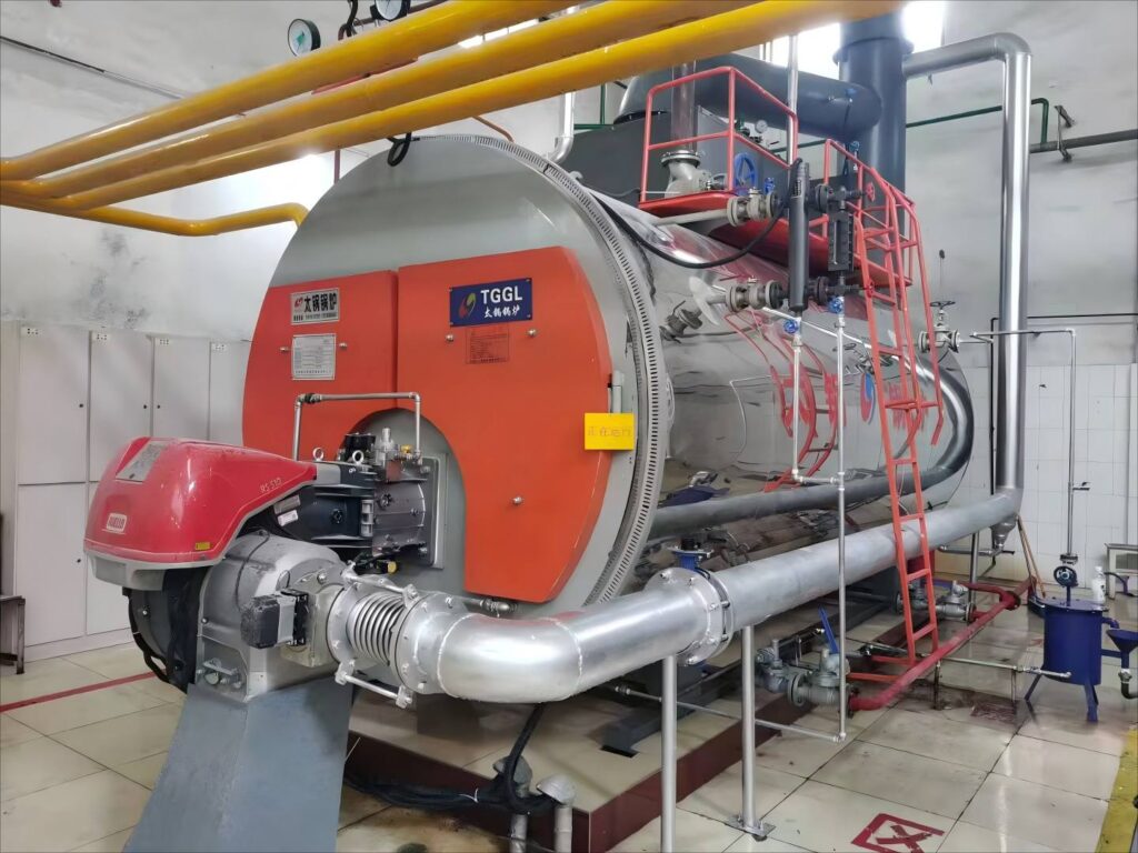
Technical Specifications
Designing a thermal utility facility requires far more than placing a boiler inside an empty warehouse. A high-efficiency industrial boiler room design integrates thermodynamic machinery, fuel supply trains, high-pressure piping networks, and advanced life-safety systems. It establishes a coordinated plant ecosystem where fuel, air, and water convert safely into dry process steam.
Improper planning generates severe long-term consequences. Inadequate clearances turn basic maintenance into costly structural overhauls. Poor ventilation causes burner flame instabilities, elevated fuel consumption, and carbon monoxide accumulation. Tight piping layouts trigger dangerous thermal stress, pipe vibration, and premature gasket blowouts.
This engineering guide outlines the core principles of industrial boiler room design, covering spatial layouts, essential equipment lists, ventilation physics, piping routing, and critical safety codes.
What Is an Industrial Boiler Room?
An industrial boiler room—or boiler house—functions as the thermal heart of a manufacturing facility. It converts chemical or electrical energy into pressurized steam, which it distributes across production floors.
Gas trains, fuel oil pumping stations, biomass silos & feeding chutes
Thermal degassing, RO purification, scale & dissolved O₂ pitting control
Three-pass thermal evaporation producing dry saturated or superheated steam
Main steam headers, local PRV stations, moisture separators & main traps
Condensing economizers, draft fans, multicyclones & insulated stacks
Pressurized return piping, surge tanks & 85°C+ sensible heat reclamation
BMS burner management, PLC staging, dual low-water fuel cutoffs & overpressure relief trains
Rather than treating the boiler as an isolated appliance, engineering teams treat the boiler room as a complete mechanical process plant. The layout must balance fluid flows, mechanical service clearances, combustion dynamics, and operational egress.
Key Considerations in Industrial Boiler Room Design
Before drawing physical floor plans or pouring equipment pads, engineers must establish overarching system parameters.
Determine total steam MCR and single vs. N+1 modular units.
Calculate boiler skid footprint, economizer envelope, and ceiling height.
Map flue tube removal clearance, burner door swing, and roll-in paths.
Transmit operating flooded weight, foundation pads, and seismic anchors.
1. Boiler Capacity and Unit Redundancy
System engineers finalize total steam demand, peak hourly loads, and system redundancy before developing an industrial boiler room design.
- Single Unit vs. Multi-Unit Battery: A single 10-ton/hour (TPH) boiler minimizes capital cost and floor area. However, it provides zero redundancy during regulatory inspections or tube cleaning. Installing two 5-TPH boilers or three 3.5-TPH boilers ensures production continuity when one unit is offline.
- Lead/Lag Modulation: A multi-boiler battery allows automated lead/lag sequencing. When steam demand drops during night shifts, the control panel shuts down lag boilers. This prevents low-load burner short-cycling and optimizes seasonal fuel efficiency.
- Future Capacity Expansion: Industrial boiler room design should always reserve structural floor space, foundation knock-out pads, and manifold connection stubs for future boilers.
2. Boiler Room Dimensions and Equipment Headroom
Boiler room dimensions depend on equipment envelope sizes, safety clearances, and overhead piping runs.
- Vertical Headroom Clearances: Boilers require substantial overhead space. Operators need vertical clearance to service top-mounted steam stop valves, replace safety relief valves, and maintain high-pressure feedwater lines. Firetube boilers require overhead access to level controls, while vertical and water-tube boilers require clearance for top drum access.
- Tube Pull Clearances: Horizontal firetube boilers (such as WNS series three-pass boilers) require dedicated clearance directly in front of or behind the pressure vessel. Technicians must open front and rear smokebox doors to brush, punch, or replace smoke tubes without demolishing external building walls.
- Burner Swing Clearances: Modern monoblock and dual-fuel burners swing open on heavy hinges for nozzle, diffuser, and ignition electrode servicing. Layouts must leave ample space around the burner housing so it can open past 90 degrees without striking columns or fuel manifolds.
Engineering Rule: Always verify local municipal building codes, National Board regulations, and ASME/EN standards for minimum legal walkway widths. Clearances generally require at least 1.0 to 1.5 meters of unobstructed passage around all operating machinery.
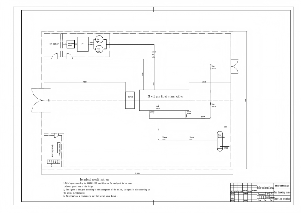
Industrial Boiler Room Layout: Mass and Energy Flows
A high-performance plant separates utilities into dedicated operational zones. This prevents hot steam pipes, high-voltage electrical panels, chemical treatment skids, and volatile fuel supplies from interfering with one another.
The design creates three closed operational circuits:
- The Water-to-Steam Circuit: Raw water flows through softening or RO filtration, enters the deaerator tank, flows through modulating high-pressure feed pumps, enters the boiler, boils into steam, and discharges into the main header.
- The Air-to-Flue Circuit: Fresh combustion air enters through louvers, mixes with fuel inside the burner, combusts in the furnace chamber, transfers heat through the convection tubes, passes through an external condensing economizer, and exhausts up the stack.
- The Condensate Recovery Circuit: Clean process condensate returns from factory steam traps into an atmospheric or pressurized return tank, pumping straight back into the deaerator to conserve thermal energy and water treatment chemicals.
Boiler Room Equipment List
An industrial boiler room requirements checklist extends far beyond the pressure vessel itself. The balance of plant includes several critical utility subsystems:
| Equipment Category | Primary Equipment Item | Core Engineering Function | Typical Position in Layout |
|---|---|---|---|
| Steam Generation | Packaged Steam Boiler | Generates saturated or superheated steam | Central equipment floor |
| Combustion | Modulating Gas/Oil Burner | Regulates air-to-fuel ratio and combustion | Mounted to boiler front door |
| Feedwater | Multi-Stage Centrifugal Pumps | Delivers high-pressure feedwater to boiler | Adjacent to feedwater tank |
| Storage | Feedwater Tank / Deaerator | Stores thermal reserve and removes O₂ / CO₂ | Elevated platform / mezzanine |
| Treatment | Automatic Water Softener / RO | Removes scaling hardness ions (Ca²⁺, Mg²⁺) | Dedicated chemical room |
| Distribution | Main Steam Distribution Header | Balances pressure and distributes plant lines | High-level along primary wall |
| Safety | Spring-Loaded Safety Valves | Prevents vessel rupture during emergencies | Top of boiler pressure vessel |
| Blowdown | Continuous & Bottom Blowdown | Discharges sludge and controls dissolved solids (TDS) | Low trench adjacent to vessel |
| Heat Recovery | Condensing Economizer | Preheats feedwater using exhaust gas heat | Mounted at rear boiler outlet |
| Exhaust | Double-Wall SS Chimney | Discharges flue gases at compliant elevations | Roof or self-supporting pad |
| Condensate | Condensate Receiver Skid | Collects and pumps hot returned condensate | Low floor level / pit collector |
| Dosing | Automated Dosing Skids | Meters oxygen scavengers and pH buffers | Adjacent to feedwater storage |
| Automation | Centralized PLC Control Cabinet | Monitors flame signals, water levels, and pressure | Isolated, climate-stable zone |
How to Arrange Boilers and Auxiliary Equipment
Segmenting the industrial boiler room design into five functional zones ensures smooth operations, clean cable routing, and safe maintenance access.
- • Main Steam Distribution Header with moisture separators
- • Blowdown flash tank & quench cooling vessel
- • Pressurized condensate receiver pump stations
- • Duplex Water Softeners / RO purification units
- • Chemical dosing pumps & water quality sampling racks
- • Brine saturation tanks & dry salt replenishment storage
- • Industrial Packaged Boilers (Units 1, 2, 3 battery)
- • Modulating gas/oil burners & air intake housings
- • Rear condensing economizers & transfer breeching
- • Elevated Thermal Deaerator Unit (O₂/CO₂ degassing)
- • Multi-stage VFD feedwater booster & main pumps
- • Feedwater blend preheaters & high-pressure manifolds
- • Primary Exhaust Breeching Lines with expansion joints and test ports
- • Particulate collectors / multicyclone & baghouse filters (Biomass/solid fuel lines)
- • Free-standing double-wall structural chimney stack with insulated roof curb penetration seals
1. Primary Boiler Generation Zone
Position boilers centrally to simplify piping runs. Anchor boilers on elevated concrete housekeeping pads (100 mm to 150 mm above finished floor level). Concrete plinths protect the boiler base frame from corrosion during washdowns and provide a level foundation for vibration isolation.
2. Water Preparation and Treatment Zone
Isolate salt storage, chemical drums, and water-softening skids from sensitive electronics. Spilled brine accelerates floor and metal structural corrosion. Place water treatment systems near drainage trenches and eye-wash stations to facilitate resin regeneration and chemical loading.
3. Elevated Feedwater and Deaerator Zone
Elevate the thermal deaerator tank on an engineered structural mezzanine above the feedwater pumps. Feedwater pumps draw boiling, saturated water at 105°C. Elevating the storage vessel provides adequate Net Positive Suction Head Available (NPSHA), which prevents pump cavitation and impeller damage.
4. Steam Distribution Zone
Mount the main steam header horizontally along a clear structural wall or an engineered overhead pipe bridge. Keep the header accessible via a catwalk. This allows operators to easily read pressure gauges, service isolation valves, and inspect inverted bucket steam traps without climbing portable ladders.
5. Exhaust and Flue Gas Zone
Direct rear breeching runs toward exterior walls to keep ducting runs short. Every 90-degree elbow in a flue adds backpressure, increasing burner fan power draw. Keep flue duct expansion joints accessible for routine thermal displacement checks.
Boiler Room Ventilation and Combustion Air
Inadequate ventilation remains one of the most common causes of industrial boiler failure. Boilers require substantial volumes of fresh air to support fuel combustion, cool external burner casings, and purge ambient heat from the building.
1. Combustion Air Calculation
Every kilogram of fuel burned requires a specific volume of stoichiometric air, plus an excess air margin (typically 10% to 20% for natural gas):
- Burning 1.0 m3 of natural gas requires approximately 10.5 to 11.5 m3 of clean air.
- Burning 1.0 kg of diesel oil requires approximately 13.5 to14.5m3 of clean air.
If an undersized louver starves the burner of oxygen, incomplete combustion occurs. This generates dangerous carbon monoxide (CO), creates soot on heat-transfer surfaces, and increases fuel consumption.
2. Louver Placement Architecture
- Low-Level Inlets: Install exterior fresh air intake louvers at low levels (typically 300 mm to 500 mm above finished floor level), positioned behind the boiler units. This brings fresh combustion air across the floor toward the burner suction openings.
- High-Level Relief Outlets: Install hot air exhaust louvers at the highest point of the boiler house roof or wall. Warm air rises by natural convection. These high-level openings exhaust waste heat from steam pipes, preventing room ambient temperatures from exceeding 40°C.
- Avoid Negative Room Pressure: A boiler room should never experience negative draft pressure. Negative pressure pulls flue gases backward through draft hoods and starves burners of air. If mechanical intake fans are used, interlock them electrically with the burner control panel. This prevents the burner from firing if the intake fans fail.
Industrial Boiler Room Safety Requirements
Operating high-pressure, high-temperature equipment requires strict adherence to international safety standards (such as ASME Section I, NFPA 85, EN 12953, and local fire codes).
1. Overpressure Protection Architecture
Every steam boiler must feature independent, certified safety relief valves sized to relieve 100% of maximum steaming capacity without exceeding maximum allowable working pressure (MAWP) by more than 6% to 10%.
- Direct External Venting: Never vent safety valve exhaust pipes into the boiler room. Route heavy-gauge vent stacks through the roof to a safe outdoor location.
- Drip-Pan Elbows: Install drip-pan elbows at the base of safety valve discharge risers. Thermal expansion must not place mechanical weight or bending stress onto safety valve bodies. Ensure drip-pan drainage holes remain open to prevent rainwater from pooling on valve discs.
2. Water Level Cut-Off Safety
Low water levels expose metal firetubes and furnace crowns to direct combustion heat without water cooling, causing rapid furnace collapse or shell rupture.
- Install two independent Low-Water Fuel Cut-Off (LWFCO) devices using distinct sensing principles (such as conductivity probes and float controls).
- The primary cut-off shuts down the burner and triggers an audible alarm.
- The secondary cut-off acts as a hard safety lockout that requires manual on-site reset by an operator.
3. Fuel Gas Safety and Leak Detection
- Gas Detection Grid: Install industrial methane/LPG sensors above gas trains and near ceilings. Interlock detectors to emergency shut-off valves.
- Automatic Slam-Shut Valves: Place double block-and-bleed safety shutoff valves on exterior fuel lines entering the building. Detectors or emergency stop trips instantly shut these valves, cutting fuel outside the room.
- High/Low Gas Pressure Switches: Pressure switches verify that gas supply pressure stays within certified burner limits before ignition begins.
4. Emergency Egress and Architectural Clearances
- Dual Exit Architecture: Any boiler room exceeding 50 m2 or housing boilers rated over 1,000 kW should have at least two separate exit doors.
- Outward Opening Doors: Exit doors must swing outward in the direction of escape and feature heavy-duty push-bar panic hardware. They must never lock from the inside.
Steam Piping Design and Layout Fundamentals
Steam piping networks expand and contract under severe thermal cycles. Poor piping design creates massive mechanical stresses that can crack boiler nozzles and blow out line gaskets.
- Top-Entry Header Connections: Always enter the main steam header from the top using 90-degree sweep bends. Dropping branch lines into the top of the header prevents condensate from flowing into idle equipment lines during shutdowns.
- Thermal Expansion Management: Steam pipes carrying 10-barg saturated steam reach 184°C. Steel lines expand roughly 1.5 to 2.0 mm per linear meter. Incorporate flexible pipe layouts, directional anchors, guide brackets, and expansion loops to absorb movement without stressing boiler nozzles.
- Continuous Pipe Pitch and Trapping: Pitch steam distribution lines downward in the direction of steam flow at a minimum slope of 1:100 (10 mm drop per 1 meter of run). Install condensate collecting pockets with thermodynamic or float steam traps every 30 to 50 meters and at the base of all vertical risers to prevent destructive water hammer.
Gas Boiler Room vs. Biomass Boiler Room Design
The selected fuel source directly dictates room footprint, civil requirements, structural loading, and auxiliary equipment spacing.
| Architectural Parameter | Natural Gas Boiler Room (WNS Series) | Biomass / Solid Fuel Boiler Room (SZL Series) |
|---|---|---|
| Fuel Storage Location | Zero YardZero on-site footprint (utility pipeline) | Outdoor BulkLarge outdoor fuel yard, silo, or enclosed bunker |
| Fuel Handling Equipment | Enclosed mechanical gas valve train | Screw conveyors, bucket elevators, hydraulic rams |
| Ash Collection Systems | Zero AshZero ash produced; zero footprint | Submerged ash conveyors, scraper troughs, bins |
| Flue Particulate Control | Direct stack exhaust with economizer | Multi-cyclone collectors, baghouses, induced draft (ID) fans |
| Building Footprint Size | CompactStandard single-enclosure footprint | 3× to 5× LargerExpanded total plant & transfer area |
| Foundation Load Rating | Standard industrial concrete floor pads | Reinforced piling to support heavy boiler and ash systems |
| Combustion Control | Fully automated electronic modulation | Grate speed control, primary/secondary airflow balancing |
Common Boiler Room Design Mistakes
Avoiding these common engineering and civil layout pitfalls will prevent costly plant revisions:
- Freezing Room Architecture Prematurely: Designing building envelopes before verifying equipment dimensions leaves rooms too small for balance-of-plant skids.
- Ignoring Tube Extraction Clearances: Forgetting tube-pull clearance forces maintenance crews to knock down external walls during major overhaul cycles.
- Restricting Combustion Air Louvers: Sizing louvers like standard room windows starves burners of combustion air, driving up fuel bills.
- Imposing Rigid Piping Loads on Boilers: Connecting rigid pipes to the boiler without flexible loops transfers expansion loads directly onto nozzles.
- Mixing Chemical Storage with Electronics: Chemical vapors from open brine or water treatment tanks corrode PLC components and motor starters.
- Ignoring Condensate Return Systems: Dumping hot condensate wastes treated water, fuel, and feedwater deaeration capacity.
- Neglecting Net Positive Suction Head: Installing deaerators without enough elevation causes high-temperature feedwater pumps to cavitate and fail.
- Ignoring Local Environmental Codes: Building short stacks without verifying local regulations risks immediate environmental citations.
What Technical Data Is Needed for Industrial Boiler Room Design?
To develop an accurate equipment layout, structural plan, and piping diagram, gather the following baseline project parameters:
- Steam Demand Metrics: Total required boiler capacity (tons/hour or kW), average and peak loads, and planned operating shifts.
- Operating Steam Pressure: Required boiler working pressure and target distribution pressure at process connections.
- Fuel Specifications: Natural gas supply pressure and line size, light oil grade, or biomass fuel properties (moisture content, sizing, heating value).
- Building Dimensions: Detailed site drawings, overhead truss heights, structural column grids, and underground utility entry points.
- Water Quality Analysis: Raw water hardness, silica content, total dissolved solids (TDS), pH, and supply line pressure.
- Condensate Return Estimates: Percentage of returned condensate, return line pressure, and return temperatures.
- Local Environmental Standards: Maximum permissible NOx, SOx, and particulate emissions limits, along with required stack discharge heights.
- Geographical and Seismic Data: Facility elevation above sea level, outdoor design temperature extremes, and seismic zone classifications.
Frequently Asked Questions
How much space should be left around an industrial steam boiler?
Maintain at least 1.0 to 1.5 meters of unobstructed walkway space around the sides and rear of the boiler for routine inspection and valve servicing. In front of the boiler, maintain a clear space equal to or greater than the total length of the boiler pressure vessel to allow for tube inspection, cleaning, and replacement.
Can an industrial boiler room be located in a building basement?
Basement boiler room installations face severe regulatory restrictions. Most jurisdictions prohibit high-pressure gas or LPG boilers in basements due to fuel gas pooling risks and limited combustion air access. Where permitted, basement installations require high-capacity mechanical ventilation, explosion-relief panels, and automated gas isolation shutoffs. Placing boiler rooms on ground-level pads with an exterior wall remains the industry standard.
Why do feedwater deaerator tanks need to be elevated?
Deaerators hold water at its boiling point (100°C to 105°C). Centrifugal pumps create a localized pressure drop at their impeller eyes. If the incoming water lacks sufficient Net Positive Suction Head(NPSHA) , the water flashes into vapor bubbles that implode violently against the impeller. Elevating the deaerator 4 to 6 meters above the pump provides the static head required to prevent cavitation.
What is the recommended ceiling height for an industrial boiler room?
Ceiling height should provide at least 1.5 to 2.0 meters of clear headroom above the highest boiler mounted valve or header platform. For medium-capacity horizontal boilers, this typically requires finished clear ceiling heights of 5.0 to 7.0 meters. This provides space for overhead steam distribution lines, safety valve discharge stacks, and monorail hoists.
How often should combustion air louvers be inspected?
Inspect air intake louvers monthly. Clean accumulated dirt, dust, and insect screens regularly. Never block, board up, or reduce the open area of combustion air louvers, especially during cold winter months.
Request a Preliminary Boiler Room Layout Assessment
A safe, efficient boiler house requires more than just choosing a boiler unit. Equipment spacing, piping runs, water treatment loops, combustion ventilation, and safety interlocks must be engineered as an integrated system.
Our technical engineering team can prepare a preliminary layout and equipment recommendation based on your project parameters.
Please share your site requirements:
- Required steam capacity (TPH) and operating pressure
- Number of boilers and standby redundancy requirements
- Primary fuel choice (natural gas, diesel, biomass)
- Available building dimensions or layout drawings
- Water treatment and condensate return parameters
- Project geographic location and elevation